Product Description
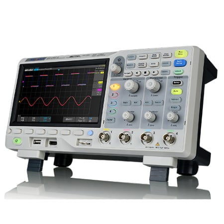
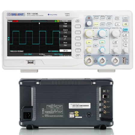
Hantek DSO5102P Oscilloscope
Karya Mandiri Techindo has a wide range of Hantek products – search by type, or model, or filter by brand to find the one you are after. If you still can’t find it contact us..
Features Hantek DSO5102P Oscilloscope
- 100MHz bandwidths.
- 1GSa/s Real Time sample rate.
- Large (7.0-inch) color display,WVGA(800×480)
- Record length up to 40K
- Trigger mode: edge/pulse width/line selectable video/slop/overtime etc.
- USB host and device connectivity, standard.
- Multiple automatic measurements.
- Four math functions, including FFTs standard.
- Provides software for PC real-time analysis.
Specifications Hantek DSO5102P Oscilloscope
| Model | DSO5102P |
| Acquisition | |
| Sample Rate | Real-Time Sample: 1GS/s |
| Acquisition Modes | |
| Normal | Normal data only |
| Peak Detect | High-frequency and randon glith capture |
| Average | Wavefom Average, selectable 4,8,16,32,64,128 |
| Inputs | |
| Inputs Coupling | AC, DC, GND |
| Inputs Impendance | 1MΩ±2% ‖20pF±3pF |
| Probe Attenuation | 1X, 10X |
| Supported Probe Attenuation Factor | 1X, 10X, 100X, 1000X |
| Maximum Input Voltage | CAT I and CAT II: 300VRMS (10×), Installation Category; CAT III: 150VRMS (1×); Installation Category II: derate at 20dB/decade above 100kHz to 13V peak AC at 3MHz* and above. For non-sinusoidal waveforms, peak value must be less than 450V. Excursion above 300V should be of less than 100ms duration. RMS signal level including all DC components removed through AC coupling must be limited to 300V. If these values are exceeded, damage to the oscilloscope may occur. |
| Horizontal System | |
| Sample Rate Range | 500MS/s–1GS/s |
| Waveform Interpolation | (sin x)/x |
| Record Length | 40K |
| SEC/DIV Range | 4ns/div to 40s/div |
| Sample Rate and Delay Time Accuracy |
±50ppm(at over any ≥1ms time interval) |
| Position Range | 20ns/div to 80us/div; (-8div x s/div) to 40ms; 200us/div to 40s/div; (-8div x s/div) to 400s |
| Delta Time Measurement Accuracy (Full Bandwidth) |
Single-shot, Normal mode:± (1 sample interval +100ppm × reading + 0.6ns); >16 averages:± (1 sample interval + 100ppm × reading + 0.4ns); Sample interval = s/div ÷ 200 |
| Vertical System | |
| Vertical Resolution | 8-bit resolution, all channel sampled simultaneously |
| Position Range | 2mV/div to 10V/div |
| Bandwidth | 100MHz |
| Rise Time at BNC( typical) | 3.5ns |
| Analog Bandwidth in Normal and Average modes at BNC or with probe, DC Coupled | 2mV/div to 20mV/div, ±400mV; 50mV/div to 200mV/div, ±2V 500mV/div to 2V/div, ±40V; 5V/div, ±50V |
| Math | +, -, *, /, FFT |
| FFT | Windows: Hanning, Flatop, Rectamgular, Bartlett, Blackman; 1024 sample point |
| Bandwidth Limit | 20MHz |
| Low Frequency Response (-3db) | ≤10Hz at BNC |
| DC Gain Accuracy | ±3% for Normal or Average acquisition mode, 5V/div to 10mV/div; ±4% for Normal or Average acquisition mode, 5mV/div to 2mV/div |
| DC Measurement Accuracy, Average Acquisition Mode |
When vertical displacement is zero, and N ≥16:± (3% × reading + 0.1div + 1mV) only 10mV/div or greater is selected; When vertical displacement is not zero, and N≥16: ± [3% × (reading + vertical position) + 1% of vertical position + 0.2div]; Add 2mV for settings from 2mV/div to 200mV/div; add 50mV for settings from 200mV/div to 5V/div |
| Volts Measurement Repeatability, Average Acquisition Mode |
Delta volts between any two averages of ≥16 waveforms acquired under same setup and ambient conditions |
| Trigger System | |
| Trigger Types | Edge, Video, Pulse, Slope, Over time, Alternative |
| Trigger Source | CH1, CH2, EXT, EXT/5, AC Line |
| Trigger Modes | Auto, Normal, Single |
| Coupling Type | DC, AC, Noise Reject, HF Reject, LF Reject |
| Trigger Sensitivity (Edge Trigger Type) |
DC(CH1,CH2): 1div from DC to 10MHz; 1.5div from 10MHz to 100MHz; 2div from 100MHz to Full; DC(EXT): 200mV from DC to 100MHz; 350mV from 100MHz to 200MHz; DC(EXT/5): 1V from DC to 100MHz;1.75V from 100MHz to 200MHz; AC: Attenuates signals below 10Hz; HF Reject: Attenuates signals above 80kHz LF Reject: Same as the DC-coupled limits for frequencies above 150kHz; attenuates signals below 150kHz |
| Trigger Level Range | CH1/CH2: ±8 divisions from center of screen; EXT: ±1.2V; EXT/5:±6V |
| Trigger Level Accuracy( typical)Accuracy is for signals having rise and fall times ≥20ns | CH1/CH2: 0.2div × volts/div within ±4 divisions from center of screen; EXT: ± (6% of setting + 40mV); EXT/5: ± (6% of setting + 200mV); |
| Set Level to 50%(typical) | Operates with input signals ≥50Hz |
| Video Trigger | |
| Video Trigger Type | CH1, CH2: Peak-to-peak amplitude of 2 divisions; EXT: 400mV; EXT/5: 2V |
| Signal Formats and Field Rates, Video Trigger Type | Supports NTSC, PAL and SECAM broadcast systems for any field or any line |
| Holdoff Range | 100ns ~ 10s |
| Pulse Width Trigger | |
| Pulse Width Trigger Mode | Trigger when (< , >, = , or ≠); Positive pulse or Negative pulse |
| Pulse Width Trigger Point | Equal: The oscilloscope triggers when the trailing edge of the pulse crosses the trigger level. Not Equal: If the pulse is narrower than the specified width, the trigger point is the trailing edge. Otherwise, the oscilloscope triggers when a pulse continues longer than the time specified as the Pulse Width. Less than: The trigger point is the trailing edge. Greater than (also called overtime trigger): The oscilloscope triggers when a pulse continues longer than the time specified as the Pulse Width |
| Pulse Width Range | 20ns ~ 10s |
| Slope Trigger | |
| Slope Trigger Mode | Trigger when (< , > , = , or ≠ ); Positive slope or Negative slope |
| Slope Trigger Point | Equal: The oscilloscope triggers when the waveform slope is equal to the set slope. Not Equal: The oscilloscope triggers when the waveform slope is not equal to the set slope. Less than: The oscilloscope triggers when the waveform slope is less than the set slope. Greater than: The oscilloscope triggers when the waveform slope is greater than the set slope. |
| Time Range | 20ns ~ 10s |
| Overtime Trigger | |
| Over Time Mode | Rising edge or Falling edge |
| Time Range | 20ns ~ 10s |
| Alternative Trigger | |
| Trigger on CH1 | Internal Trigger: Edge, Pulse Width, Video, Slope |
| Trigger on CH2 | Internal Trigger: Edge, Pulse Width, Video, Slope |
| Trigger Frequency Counter | |
| Readout Resolution | 6 digits |
| Accuracy (typical) | ±30ppm (including all frequency reference errors and ±1 count errors) |
| Frequency Range | AC coupled, from 4Hz minimum to rated bandwidth |
| Signal Source | |
Hantek DSO5102P – Manual
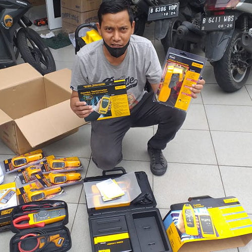
Produk asli Kami distributor langsung Hantek . Harga murah dan berkualitas bergaransi tentunya. dapat di kirim ke seluruh wilayah indonesia.
Dalam pengiriman produk yang pelanggan beli, sebelumnya sudah kami cek untuk memastikan produk dalam keadaan baik dan siap kirim.